> All models are wrong, but some are useful.
## Table of Contents
1. [[#Introduction]]
2. [[#How to read this post if...]]
3. [[#Hard(ware) foundations]]
4. [[#SystemVerilog scheduler]]
5. [[#Simple illustration]]
6. [[#More motivation]]
7. [[#Resolving race conditions in subscribers]]
- [[#Other solutions for the subscriber]]
- [[#Use non-zero delay]]
- [[#Prevent the race condition with a single interface]]
- [[#Prevent the race condition with early delay]]
- [[#Use assertions]]
8. [[#Reacting to combinational logic]]
- [[#Betrayal in simulation]]
- [[#Other solutions for the driver]]
- [[#Restructure RTL]]
- [[#Place combinational logic between the driver and DUT]]
1. [[#Conclusion]]
## Introduction
Every so often, I encounter concepts that seem obvious to me, but that puzzle other people. One of such concepts is non-blocking assignment in SystemVerilog. This includes not just how it works, but why it exists in HDL languages while being absent from programming languages. While this may be obvious to those with an electronics background, people come to our field from diverse backgrounds. Even if the question comes from a recent electronics engineering graduate, I can't blame them for sleeping through lectures where an old professor mumbled something about transistor's transfer characteristic. We won't stop at a simple explanation of non-blocking assignments, of course — that would be unforgivably boring — and will also touch on the topic of race conditions and glitches. Let's start small and see how deep is the rabbit hole.
Each time a reference to LRM is given, it should be treated as IEEE-1800-2023.
## How to read this post if...
### ... you feel that the introduction speaks about you
Just read it completely.
### ... NBAs are trivial for you, but "delta-cycle delay" doesn't ring a bell
Start with [[#Resolving race conditions in subscribers]].
### ... ~~you're a cat~~ have dealt with pesky delta-cycle delays already
In this case, I may not be able to tell you anything you don't know already. However, I will point to the sections where I learned something new while writing this post.
- [[#Use non-zero delay]]
- [[#Betrayal in simulation]]
## Hard(ware) foundations
The syntax of the non-blocking assignment is as simple as it gets: `a <= b` in contrast to the blocking assignment `a = b`. How does it work? In simple terms, it evaluates the value of `b` (which can be an expression) and updates the value of `a` *sometime later*. On the contrary, for the blocking assignment there's no delay: `a` is updated when simulator encounters the assignment. Before explaining what *sometime later* means, which will require learning the joys of SystemVerilog scheduler, let's check *why* it works like this.
There are two fundamental entities in the digital design: a logic gate and a flip-flop.
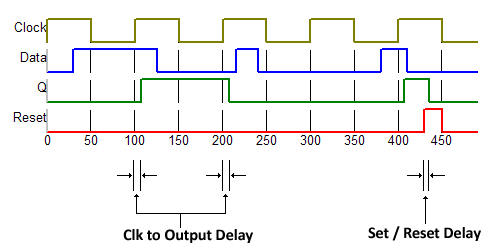
A typical D flip-flop without an enable signal updates its output on every clock posedge. What's crucial here is that the flip-flop output does not update instantly. Instead, it settles to the new value after a short delay known as the clock-to-output delay. While often omitted from waveforms, some viewers, like WaveDrom, visualize it explicitly.
![[wavedrom.png]]
The fact that a flip-flop has a non-zero clock-to-output delay means that when its input changes in sync with a clock edge (as the output of another flop, possibly passing through some combinational logic), the receiving flip-flop will not see the new value until the _next_ clock edge.
![[2flops.png]]
This behaviour is fundamental to how hardware works, and any hardware description language must reflect it. Programming languages, on the other hand, don't model hardware and thus simply don't have a necessity for something apart from a typical assignment.
But how should we represent this timing in HDL? The actual clock-to-output delay depends on the technology, and in practice it's always much shorter than the clock period. When modeling in HDL like Verilog, we intentionally abstract away these physical details since they're irrelevant to functionality. The actual clock period is often irrelevant too. Verilog and SystemVerilog provide a one-size-fits-all solution: assignments executed at the clock edge take effect only after all code triggered by that clock edge has executed, but without advancing simulation time.
In other words, the delay in assigning the left-hand side of a non-blocking assignment is 0 ns, but not instant. This is, of course, not how real hardware behaves, but that's close enough and for the *model* of the hardware that's good enough, because it clearly separates the moments of sampling the input values from updating the output values. This way the language allows to model flip-flops without even thinking of actual delays.
To talk about events, happening sequentially, or, in other words, with a delay to each other, but without advancing the simulation time, we use the term *delta-cycle delays*. Even though this term is not defined by the language specification, it's widely used in the industry to denote something that happens inside a single simulation timestamp. As you will soon realize, there is a lot going on inside a timestamp.
## SystemVerilog scheduler
To understand how this works, we need a brief look at the SystemVerilog scheduler. The simulator processes events in specific regions: Active, Inactive, and NBA (Non-Blocking Assignment). That's what happens in each of them:
- When a clock edge triggers processes, they execute in the **Active region**. Blocking assignments take effect immediately within this region. Encountering `#0` suspends the process and moves it into the **Inactive region** (LRM 4.4.2.3). Encountering an NBA evaluates the right-hand side and schedules the execution for the NBA events region.
- When simulator reaches the Inactive region, and it's not empty, the processes there are moved into the Active region and simulator starts another iteration of the Active region.
- In the **NBA event region**, the left-hand side of assignments are updated.
Below is the part of the Figure 4-1 from the LRM. Only Active, Inactive and NBA slots matter to us in the scope of our discussion.
![[Blog/Scheduling/Scheduler.png]]
Even though simulators take care of the scheduling, knowing how it works is crucial because every verification engineer will eventually encounter **race conditions** in their testbenches: situations where simulation results depend on the ordering of concurrent events within a delta-cycle, which is not guaranteed by the language. To resolve it, and, even better — foresee — you have to know what exactly happens behind the curtain. Let's create such situations artificially and see how knowing all this helps us.
## Simple illustration
First, let's see what happens when we use only blocking assignments. There are two modules: `producer` and `consumer`. Both use `posedge clk` to work with data.
```verilog
module producer(
input wire logic clk,
output var logic [7:0] data
);
always @(posedge clk) begin
data = $urandom_range(0, 255);
$display("[%0t] Data produced: %d", $time, data);
end
endmodule
module consumer(
input wire logic clk,
input wire logic [7:0] data
);
always @(posedge clk) begin
$display("[%0t] Data consumed: %d", $time, data);
end
endmodule
module producer_consumer_tb;
bit clk;
logic [7:0] data;
always #5 clk = ~clk;
producer u_producer(.*);
consumer u_consumer(.*);
initial begin
#26 $finish;
end
endmodule
```
The output produced is
```
[5] Data produced: 54
[5] Data consumed: 54
[15] Data produced: 60
[15] Data consumed: 60
[25] Data produced: 125
[25] Data consumed: 125
```
If we change the order of instantiations of modules, the output becomes
```
[5] Data consumed: x
[5] Data produced: 54
[15] Data consumed: 54
[15] Data produced: 60
[25] Data consumed: 60
[25] Data produced: 125
```
The simulation results become dependent on something that should not have any effect in the properly written design. This is exactly what we call a race condition. Using non-blocking assignment prevents it because now the order of execution is guaranteed by the language.
You can check yourself that the situation improves when the assignment is changed to the non-blocking one. Take care, however. What would you expect to be displayed in the following code? Is there a race condition?
```verilog
always @(posedge clk) begin
data <= $urandom_range(0, 255);
$display("[%0t] Data produced: %d", $time, data);
end
```
Strictly speaking, no, because we **expect** `$display` to be executed in the Active region, while `data` will be updated only later, in the NBA region.
Let's try something more tricky. LRM 4.8 contains a good example of the race condition:
```verilog
assign p = q;
initial begin
q = 1;
#1 q = 0;
$display(p);
end
```
Both `$display` and `assign` are executed in the Active region. SystemVerilog allows simulators flexibility in process execution order within the same region, so a simulator may choose to execute `$display` first, or update the value of `p` in the `assign`. Both orders are correct according to the language specification.
Another fairly typical example of the blocking and non-blocking assignment difference is [variable swap](https://www.edaplayground.com/x/bNKr).
```verilog
module tb;
initial begin
int x = 1;
int y = 2;
$display(x, y);
x <= y;
y <= x;
#1;
$display(x, y);
end
endmodule
```
Output:
```
1 2
2 1
```
You should be able to explain why it works and what will happen if non-blocking assignments are changed into the blocking ones.
If blocking assignments in the design can cause race condition, must they be then forbidden? Not really. You can have intermediate signals computed with blocking assignments.
```verilog
always @(posedge clk) begin
logic[7:0] sqr;
sqr = a * a;
data <= sqr + b;
end
```
Though, I have heard opinions that this is blasphemy and one should always use `assign` to achieve it. I will leave the holy wars to the design experts.
## More motivation
While this was a fairly artificial example—if a flip-flop is not modeled correctly, the design unsurprisingly doesn't behave correctly—are there any non-trivial scenarios where the knowledge of scheduling semantics can help us? Sure there are, let's name a few.
- Two ports of a module output data on the same clock cycle that must be consistent with each other. The consistency must be verified in the testbench, but if the two ports are sampled by independent processes, we have a race condition. This is a fairly common problem occurring in scoreboards of complex designs.
- A DUT has a synchronous input and a combinational output, which must be considered to drive the next input. A simple example is a FIFO with `push` and `full` signals and a condition that they can't be `1'b1` at the same time. Doesn't happen as often as the previous problem in my experience, but when it does, you'd better know how to resolve it.
## Resolving race conditions in subscribers
Let's start with the first case. The DUT has two interfaces. Transactions on the first, the main interface, happen periodically. Transactions on the second, let's call them interrupts, happen only when the transactions on the main interface satisfy a certain condition. Both interfaces are clock-synchronous.
[Wavedrom.](https://wavedrom.com/editor.html?%7Bsignal%3A%20%5B%0A%20%20%7Bname%3A%20%27clk%27%2C%20%20%20%20%20%20%20wave%3A%20%27p.......%27%7D%2C%0A%20%20%7Bname%3A%20%27Main%27%2C%20%20%20%20%20%20wave%3A%20%270474.74x%27%7D%2C%0A%20%20%7Bname%3A%20%27Interrupt%27%2C%20wave%3A%20%270.10.10x%27%7D%2C%0A%20%20%7Bname%3A%20%27Intr%20data%27%2C%20wave%3A%20%27x.6x.6x.%27%7D%0A%5D%7D%0A)
![[scb_dut.png]]
The scoreboard must verify that interrupts happen if and only if the condition on the Main interface is correct. Let's draft the scoreboard now.
```verilog
class race_condition_scoreboard extends uvm_scoreboard;
`uvm_component_utils(race_condition_scoreboard)
uvm_analysis_imp_main #(main_item, race_condition_scoreboard) main_imp;
uvm_analysis_imp_interrupt #(intr_item, race_condition_scoreboard) interrupt_imp;
main_item main_queue[$];
intr_item intr_queue[$];
function bit is_intr_expected(main_item main_tr);
// ...
endfunction
function void check_interrupt(main_item main_tr, intr_item intr_tr);
// check if interrupt is correct
// intr_tr can be null if no interrupt has been received
endfunction
function void write_main(main_item t);
main_queue.push_back(t);
endfunction
function void write_interrupt(intr_item t);
intr_queue.push_back(t);
endfunction
endclass
```
Do you see the problem? Where shall we call `check_interrupt`? We cannot do it in the `write` function because there's a race condition: we don't know which transaction will be received first. Let's try resolving it in the `run_phase`
```verilog
task run_phase(uvm_phase phase);
forever begin
main_item current_main;
intr_item current_intr;
wait(main_queue.size() > 0);
current_main = main_queue.pop_front();
if (is_intr_expected(current_main)) begin
wait(intr_queue.size() > 0);
current_intr = intr_queue.pop_front();
end
check_interrupt(current_main, current_intr);
end
endtask
```
Now we have another issue: what if there's a bug in the DUT and the expected interrupt isn't generated? The proper approach will be:
1. Wait for an interrupt-generating main transaction.
2. Wait for *some time*.
3. Check for the interrupt transaction.
How long shall we wait? Remember that NBA happens in a special scheduling region, when it's guaranteed that all active process have been executed and are now suspended. So waiting for NBA assignment to happen is enough to resolve the race condition. In other words, we can do this in the scoreboard:
```verilog
begin
bit z;
z <= 1;
@(z);
end
```
Since it's a fairly typical operation in UVM testbenches, UVM provides a task called `uvm_wait_for_nba_region`.
```verilog
task run_phase(uvm_phase phase);
forever begin
main_item current_main;
intr_item current_intr;
wait(main_queue.size() > 0);
current_main = main_queue.pop_front();
uvm_wait_for_nba_region();
if (intr_queue.size() > 0)
current_intr = intr_queue.pop_front();
check_interrupt(current_main, current_intr);
end
endtask
```
Thus, `check_interrupt` is guaranteed to be executed when both Main and Interrupt monitor have finished collecting transaction triggered by the clock's posedge.
A follow-up question for the reader: what if the Main interface had idle cycles with no transactions collected? What issue can happen in the current implementation of the scoreboard and how to avoid it? Answer below.
```verilog
task run_phase(uvm_phase phase);
forever begin
main_item current_main;
intr_item current_intr;
// To catch spurious interrupts, wait for Main _or_ Interrupt transaction. Checking logic is hidden in check_interrupt
fork
wait(main_queue.size() > 0);
wait(intr_queue.size() > 0);
join_any
uvm_wait_for_nba_region();
if (main_queue.size() > 0)
current_main = main_queue.pop_front();
if (intr_queue.size() > 0)
current_intr = intr_queue.pop_front();
// null must be treated as event that didn't happen
check_interrupt(current_main, current_intr);
end
endtask
```
### Other solutions for the subscriber
Every problem has more than one solution, and this not an exception. Let's consider other options and think about the pros and cons.
#### Use non-zero delay
Using zero-time delays may look like a black magic to you, and it's difficult to argue against such a view. And of course, every time we wait for an NBA region, we can wait a sufficiently small non-zero amount of time for the same result. What time would it be? If you think about `#1`, you're wrong: with a timescale `1ns/1ps` many things can happen during 1 ns. And `#1ps` isn't a good option either since it depends on the time precision to be `1ps`, and you can't guarantee it won't be changed accidentally. There's a special construct in the language, however: `#1step`. In the LRM it's described only in relation to clocking blocks, but some simulators allow using it in procedural code to wait the minimal waitable time (in other words, `timeprecision`). Since it's not defined in the LRM in this context, its behaviour is simulator-dependent, and you can see that for yourself in this [EDA Playground example](https://www.edaplayground.com/x/Tn7M). Besides this obvious drawback, it has another one: when using `#1step` in checkers, the error message will be printed not in the same timestamp, where the error condition has occurred. On the positive side, `#1step`, if works, is guaranteed to resolve all delta-cycle race conditions.
#### Prevent the race condition with a single interface
We can add the interrupt signal into the main interface. There are no races if there's only one process, and consolidating signals into a convenient meaningful interface is often a practical solution. And quite often that's ill-advisable: if the Main interface is standard, e.g. AXI, then adding a custom signal ranges from nearly impossible to cumbersome, depending on how the agent is written and whether it's 3rd-party or an in-house one.
#### Prevent the race condition with early delay
We can also resolve race conditions by moving `uvm_wait_for_nba_region` to the monitor of the Interrupt interface. Now the order of appearance of transactions in the scoreboard will be defined. On the other hand, this NBA delay will impact every subscriber of the Interrupt monitor and may come as a surprise even for the future you debugging a weird bug somewhere else in the testbench.
#### Use assertions
Concurrent assertions offer a native SystemVerilog way of resolving race conditions as they use the values of signals from the **Preponed region** to evaluate the expression. You can think of the Preponed region of the scheduler as the starting point of the time slot evaluation when nothing has been updated yet. In other words, all the signals in this region hold their final values from the previous time step. However, using SystemVerilog assertions or checkers in UVM components, and which in which cases, is a test bench design decision. It's okay to have only SVA, or only UVM checkers, or both, as long as you're consistent. If you have both SVA and UVM checkers, it's important to draw a line. For example, you may decide that you check signal relations in SVA, but protocol conformance in UVM. Running to SVA as soon as you get a race condition in the test bench is not the most future-proof approach.
Note, that `assert final` doesn't resolve the race condition if used in a class (LRM 16.4). Some simulators explicitly warn that the `final` keyword has no effect when used in a class.
## Reacting to combinational logic
Let's see how we can apply our knowledge of scheduling and time regions not in a subscriber, but in a driver.
Suppose that DUT processes addresses for two memory regions. The region 0 has no limitation on frequency on input valid data. The region 1, however, is polled by another module every 4 cycles, and at the moment of polling it's invalid to send input data highlighted by `valid`. DUT outputs the `stall` signal to indicate this. So the condition `valid && stall` is invalid. DUT is below.
```verilog
module async_logic(
input clk,
input rst_n,
input valid,
input region,
output stall
);
logic [1:0] cnt;
always_ff @(posedge clk or negedge rst_n) begin
if (!rst_n) begin
cnt <= 0;
end else begin
cnt <= cnt + 1;
end
end
assign stall = region && (cnt == 0);
stall_is_honored: assert property (
@(posedge clk)
stall |-> !valid
);
endmodule
```
Below is the testbench. [Link to full EDAPlayground example](https://www.edaplayground.com/x/aa9a).
```verilog
module tb_async_logic;
bit clk;
bit rst_n;
bit [7:0] addr;
bit valid;
bit stall;
bit region;
// Instantiate DUT
async_logic dut (.*);
always #1 clk = ~clk;
initial begin
$dumpfile("dump.vcd"); $dumpvars;
end
initial begin
rst_n = 0;
valid = 0;
#4;
rst_n = 1;
#100;
$finish();
end
always @(posedge clk iff rst_n) begin
region <= $urandom_range(0, 1);
if (stall) begin
valid <= 0;
end else begin
valid <= $urandom_range(0, 1);
end
end
endmodule
```
Do you expect it to work correctly? Have a look at the way the `stall` signal is assigned and read. The value of `stall` is affected by the counter in the DUT and the region value in the testbench. These two signals are independent of each other and are updated on a clock posedge, but in the different processes. The proper setting of `valid`, however, depends on `stall`, or, in other words, on both `region` and `cnt`. So, the generation of the correct `valid` signal must happen after the new value of `stall` is visible.
By this point you should understand, that this code
```verilog
always @(posedge clk iff rst_n) begin
region <= $urandom_range(0, 1);
if (stall) begin
```
will have the `stall` value corresponding to the previous clock. Indeed, if we simulate as is, from time to time, we will see the violations of the assertion:
```
T=41 rst_n=1 cnt=1 valid=0 stall=0
T=43 rst_n=1 cnt=0 valid=1 stall=1
"testbench.sv", 21: tb_async_logic.dut.stall_is_honored: started at 45ns failed at 45ns
Offending '(!valid)'
T=45 rst_n=1 cnt=1 valid=0 stall=0
T=47 rst_n=1 cnt=0 valid=0 stall=0
```
We already know how to resolve delta-cycle race conditions, and this knowledge is easily applicable here. Because `region` and `stall` are outputs of the flip-flops and are updated in the NBA region, we can add `uvm_wait_for_nba_region` to resolve the problem.
When simulating with this update
```verilog
always @(posedge clk iff rst_n) begin
region <= $urandom_range(0, 1);
uvm_wait_for_nba_region();
if (stall) begin
```
the issue goes away.
### Betrayal in simulation
Understanding what is going on in a delta-cycle is good, but being able to actually see it is even better. Normally, for each moment of time, simulators show the final values of signal, or, speaking on the SystemVerilog language, values from *Postponed region*. But there's a way to make them display what's going on inside a delta-cycle. This option is off by default since it consumes additional resources and is rarely needed. In VCS, you have to add `+deltacycle` to the simulation.
That's how our example looks like after enabling this option on a waveform.
![[Expanded-delta-time.png]]
Here we can see the following sequence of events:
1. Clock posedge.
2. NBA of `region` takes place, and it changes to HIGH.
3. `stall` is assigned a new value after the change of `region`.
4. NBA of `cnt` takes place, and it changes to 1.
5. `stall` is updated once again and now takes the final value LOW.
6. TB samples the final value of `stall` and assigns `valid` to LOW.
Does this waveform look like you expected? To me, it looks suspicious or even worrying and that's why. NBAs are supposed to take effect in the NBA region, while normal code execution must happen in the Active region. Why do we see the delta-cycle glitch in `stall`, then? According to the LRM (or, at least, my interpretation of it), the process evaluating `stall` is supposed to sleep until NBA region is completed. But we see that there's something happening between two NBAs. The `assign stall` process which is implicitly waiting on `region` has been restarted before the second NBA took place. Can it happen then that our process blocked on `uvm_wait_for_nba_region` will be restarted before, let's say, `cnt` NBA takes place, and sample a non-final value of `stall`?
In my practice, `uvm_wait_for_nba_region` has always worked as it's supposed to work, but you should never believe a random guy's blog. When in doubt, open [EDA Playground](https://www.edaplayground.com) and check for yourself.
To answer the question above, let's rephrase it: "Given a combinational signal dependent on the outputs of flip-flops, would it be possible to sample an intermediate value of this signal?" Because we suppose that there's a glitch happening between two NBAs, the way to answer our question is to wait for the glitch explicitly.
> [!note]
> I don't have access to VCS on the moment of writing this, so I would be grateful if someone could send me the screenshot with an expanded delta-cycle for this example.
```verilog
module tb;
logic a = 1'b0;
logic b = 1'b1;
wire x = a ^ b;
initial begin
#2;
a <= 1'b1;
b <= 1'b0;
#1;
$finish;
end
initial begin
#1; // start at non-zero time to avoid potential start-of-simulation glitches
wait(x == 1'b0);
$display("wait detected glitch!!! x = %b", x);
end
initial begin
#1;
@(x);
$display("@ detected glitch!!! x = %b", x);
end
endmodule
```
None of 3 simulators report any glitches. But when doing a minimal working examples, be careful to account for all nuances. In our `stall` situation, the two signals were assigned from different processes. Let's alter the code accordingly.
```verilog
initial begin
#2;
a <= 1'b1;
// b <= 1'b0; move to another process
#1;
$finish;
end
initial begin
#2;
b <= 1'b0;
end
```
And now VCS will print
```
@ detected glitch!!! x = 1
```
Moving assignments to different processes had a profound effect. While in the first case both blocked processes remained blocked during the whole simulation, in the second case one process got unblocked. However, the value that the process observed is not a glitch, but a correct final value of the signal. What does it mean? First, `uvm_wait_for_nba_region` should work as expected: the procedural code is scheduled for execution in the Active region. Second, beware of glitches. I'm not going to dive into this topic now, but maybe in another post.
### Other solutions for the driver
#### Restructure RTL
The condition when DUT's state prevents new inputs being driven is called *backpressure*. The typical source of backpressure is `valid/ready` handshake: when the driver has valid data, it asserts valid; when consumer can process the data, it asserts `ready`. The data is flopped on a clock posedge when `valid && ready == 1'b1`. It is an ideal situation when all signals are independent, synchronous and no delays are necessary. Our DUT, however, strays from this ideal significantly: the `stall` signal, which can be viewed as `!ready`, is combinational and `valid`, which is synchronous, depends on it. In other words, in an ideal world, such a problem would not exist. Alas, in the real world, from which I took this example, we also have considerations for latency, legacy code and other boons.
#### Place combinational logic between the driver and DUT
We could have simply added an intermediate signal
```
assign valid_masked = valid && !stall
```
Connecting this signal to DUT instead of `valid` resolves the issue. On the positive side, we don't need delays any more. And it even looks natural in this example because everything is a module, but that's only for simplicity. In a UVM testbench it would've been a proper UVM driver, and we would have to add this additional code into the interface. Now the driving logic is spread between a class and an interface. That's not necessarily bad: if you aim for emulation, you probably have quite a lot of logic in an interface. But that's something to be considered in every particular case. No solution is bad just because it's bad.
## Conclusion
We have started with a fairly simple question — what is a non-blocking assignment — and seen how knowing the answer can help in resolving otherwise non-trivial verification issues and even found an apparent violation of the language specification by one of the simulators. I think this is very illustrative of nature of any engineering work: if you want to be good at your job, you cannot settle for the fact that something just works. You have to know how it works and why it works like this. Then you can come up with solutions to new problems, instead of relying on the recipes handed down to you.
As for the topic of our discussion, I hope that you now have enough knowledge to foresee and resolve the race condition in your test benches and understand that not always you have to use the quirks of the SystemVerilog scheduler to do it.