[#Spherical](https://publish.obsidian.md/#Spherical)
[TobyStuff](https://publish.obsidian.md/shanesql/TobyStuff)
The reciprocal angles are never measured. They are assumed based off the drop in the distance. It can be proven easily. There was no claimed distance.
How there are plumb line deflections that are perpendicular to their lumpy geoid which don’t match terrain or the ellipsoid…
So not only does that take away any claim of measuring spherical excess and measuring reciprocal zeniths but we also have ….
Non conformal refraction models Downward refraction models vary from country to country and state to state They all don’t agree
8
Check out these references:
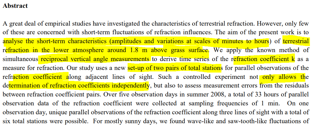
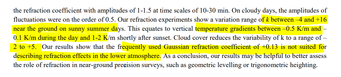
“Because of the complex process required to calculate an exact value for the refraction coefficient in every
surveying task, it has been suggested, for simplicity, that
specific values that approximate the average state of the
atmosphere be applied. Such values include the global k = 0.13 for all latitudes and for all seasons. This specific
value was introduced by C.F. Gauss for arc measurements in Hanover in 1823 and has been applied extensively ever since ([4,6])”
Gaifillia, D., et al. "Empirical modelling of refraction error in trigonometric heighting using meteorological parameters." Journal of Geosciences and Geomatics 4.1 (2016): 8-14.
Hirt, Christian, et al. "Monitoring of the refraction coefficient in the lower atmosphere using a controlled setup of simultaneous reciprocal vertical angle measurements." Journal of Geophysical Research: Atmospheres 115.D21 (2010).
- **K/m**: Kelvin per meter. This unit measures the temperature gradient, indicating how temperature changes with height in the atmosphere.
- **HPa**: Hectopascal. This is a unit of pressure, commonly used in meteorology to describe atmospheric pressure.
- **°K**: Degrees Kelvin. This unit measures absolute temperature, though it's more commonly referred to simply as Kelvin (K) without the degree symbol.
- **°C**: Degrees Celsius. This unit measures temperature relative to the freezing point of water.
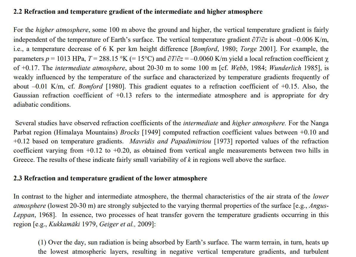
The image discusses the refraction and temperature gradients in different layers of the atmosphere, specifically the intermediate and higher atmosphere. It notes that:
- **Higher Atmosphere**: The vertical temperature gradient is about−0.006K/m, with a local refraction coefficient of +0.17.
- **Intermediate Atmosphere**: Characterized by a temperature gradient of about−0.01K/m, equating to a refraction coefficient of +0.15.
The studies mentioned report refraction coefficients with small variability:
- Brocks (1949) found values between +0.10 and +0.12.
- Mavridis and Papadimitriou (1973) reported values from +0.12 to +0.20.
"On the basis of reciprocal vertical angle measurements near Hannover (Germany), Carl Friedrich Gauss found an average value of the refraction coefficient k of approximately +0.13 [e.g., Brunner, 1984]. The Gaussian value of k is well known to the surveyor as a frequently used standard value of terrestrial refraction"
Highway Surveying Manual M 22-97
January 2005
Washington State Department of Transportation
Environmental and Engineering Service Center
Design Office
"For the coefficient of terrestrial refraction for Washington State use 0.14"
The Commonwealth of Massachusetts
Survey Manual
Massachusetts Highway Department
Metric Edition
1996
“The two errors affect elevation differences and
zenith angles in opposite directions, but the atmospheric
refraction error is only approximately 13% of the error for earth curvature.."
So you’ll notice their refraction coefficient or k value is 0.13 in some places and 0.14 in others
Though they **appear to be close they aren’t — they drastically affect drop over distance**
**And what’s more neither of them are 7/6 R**
Which is adding 0.166
So what’s the difference between 7/6 R and 0.13
That’s a 23% rate of change
The refraction coefficient, often denoted ask, is crucial in understanding how light bends in the atmosphere, affecting measurements over distance. Here's a breakdown of the differences and their impact:
1. **Refraction Coefficient Values**:
- **0.13 and 0.14**: These are typical values for the refraction coefficient used in some atmospheric conditions. Although they appear close, even small differences can significantly affect measurements over long distances.
2. **Comparison with76R**:
- The value76Rcorresponds to a refraction coefficient of approximately 0.166. This is a standard approximation used in many geodetic calculations.
- Comparing 0.13 and 0.166 shows a difference of 0.036, while the difference between 0.14 and 0.166 is 0.026.
3. **Impact on Measurements**:
- The difference between a refraction coefficient of 0.13 and the standard76R(0.166) represents a change of about 23% relative to the standard value.
- Such variations can lead to significant errors in calculating distances or angles, especially over large distances, due to the curvature of light paths.
16/13
So for measurements this gives you a 3% fudge factor depending on the model — that plus the vertical plumb line deflection and you gotta be close to a 5% error level already
So when they o**nly need arc seconds of variance with their triangular observations to go from flat to a ball**, they got plenty of wiggle room
Before systematic error and mechanical error of the theodolites they already get like a 3-5% Milligan
Gaifillia, D., et al "**Refraction is a complex problem in terrestrial optical measurement and can be regarded as a major source of systematic error in the precise determination of height differences using trigonometric weighting**." ... "
It is important to bear in mind that determination of k by means of a model may turn out to be somewhat inaccurate, but **still remains better than the blind use of a universal k of 0.16 (for Greece) or 0.13 (for other parts of Europe**).
McDaniel and Hahalov "Variations in the refractive index in the atmosphere are caused by inhomogeneities of a wide range of sizes. These include both variations in the mean refractive index and refractive index fluctuations due to turbulence that can not be accounted for by deterministic models"[11]
Baselga, et al. "If temperature vertical profiles are unknown then the refraction coefficient cannot be reliably determined. Some surveyors may customarily use then an average value, e.g. k = 0.13 , perhaps being unaware of the risks involved in such simplistic assumption."[10]
Because 0.13 is a smaller effective radius than 0.166 it means that curvature will be more pronounced
These things are limited in range out to approx 40km due mainly to their ability to be level - plumb under optimal optical conditions
And they have built in all globe reification you want automatically
So how much curvature is there factored in over a distance of 10km max?
At 8” per mile squared that’s max 26 feet of drop over max 6.25 miles. That’s how much globe padding is built
in with curvature alone. Refraction corrections add extra padding
I wish I could figure out the margin of error for one of those at 40km range.
Remember how frustrating it was for the NATO SAPPHIRE team
That’s 206 arcsecond accuracy for plumb
206 arcsecond tilt error
So the optics are precise to 1.5 arcseconds but the plumb is to 206arcseconds and this is before the fudge factor
of refraction for the optics and deflection of the vertical for plumb!
They have plenty of wiggle room for the ball.
That tilt error is 60 inches per mile.
These are most definitely not suited to measuring earth curvature
They create fudge factor they need to make the ball work with measurements they take
Curvature of the Plumbline
As stated, the deflection of the vertical changes with position along the curved
plumbline. Therefore, the deflection of the vertical at the geoid (θG) does not
necessarily equal that at the Earth’s surface (θS) and vice versa. In order to equate
these two quantities, the curvature of the plumbline between the geoid and Earth’s
surface (δθGS) is required. This quantity can not be observed directly because of the
presence of the topography, so must be estimated using a model of the Earth’s gravity
field within the topographic masses.
Featherstone, W. E., and Sixth South East Asian Surveyors’Congress.
"The use and abuse of vertical deflections."
Proc. 6th South East Asian Surveyors Congress, Fremantle, November. 1999.
[http://www.earthsurvey.us/deflecge/Featherstone.pdf](http://www.earthsurvey.us/deflecge/Featherstone.pdf)
They measure FLat. They composite the Data. Stitch it into geodal dimenions. Then they apply the fluctuation fo the plumb to
obtain the arc length.
oin flat earth local plumb, then perpendicular to horizon
on globe earth, plumb is not plumb, down to the center of the earth.
because on a globe down is only down relative to a center of mass,
and they can only determine the center of mass,
and that is a result of gravity , due to axial rotation.
they have to assume there is a gravitational flux,
so, you presuppose the spherical nature and already know the exact radius for this to work .
you must have it down to a high levelof specificity to get the angle for the plumbob,
to be clear, assumed gravity is puling us towards center of mass down, and
the nature of axial rotation , and the spherical nature of earth, so have now invoked 3 aspects of the model you intended to prove
right?
use the radius to get the angle on each plumb to get the arc length, different than a line on a flat earth,
an arc has to have the radius value to even be plotted, so therefore geodeditc surveyong cannot even be done without the radius value,
therefore cannot prove the globe model.
Also, the nature of the geoid means gravity potetnatil is eauwal everywhere and to which the firection of gravity is always perpendicular.
Because without a plane you cannot make the measurements we are talking aboput that prove the globe.
The First Deflection of the Vertical (of longitude). Was in the 1830s— well after the US Coast Survey
and other major surveys and before the Clarke ellipsoid 1866. Besides revealing the actual non
measurement of this presumed deflection (despite the eager title), this documents how the globe
is a projection onto the celestial sphere in the first instance. Intriguing historical context
behind the thought and methodology to project a flat world onto the celestial sphere.
TLDR; they look at the night sky and find that stars are not precisely where they are expected
to be at a given time and coordinate reference (using light stations). So they mathematically “corrected”
their terrestrial measurements to conform to the astronomical coordinates in the sky and called it a measurement.
[https://archive.org/details/arxiv-1403.6638](https://archive.org/details/arxiv-1403.6638)
“variance in propagation yields standard deviations of k of 0.08 - 0.15 on cloudy days and 0.19 - 0.21 for sunny days”
Earlier it says
“The standard deviation of the vertical angles is found to vary between 1.3 and 2.8 arc seconds on cloudy days and 3.4 - 3.8 arc seconds on sunny days”
okay 7/6R is inflating earths radius 16.7%
carl gauss back in the late 1800s surveyed europe and saw too far too
but he assigned a value of 13%
approximately 4% spread
the bigger the % the more they’re flattening earth and extending the horizon out
their curvature rate is not 8” per mile squared when applying 7/6R or 17% for example (edited)
hope that helps clarify— refraction flattens the earth (edited)
the gauss model of terrestrial refraction was 13%
question: what does that do to their presumed dip angle? (edited)
perpendicular doesn’t it. they thought they’d have to tilt to account for curvature but when they apply a refraction correction they don’t
mathematically they are flattening earth to match what’s going on
@bluemarbelscience
- things you should address before worrying about the inclusion of the british mesh for comparison :
1. The adherence to a predefined spheroid model as outlined on page,
2. the adjustment table for various longitudes employed for azimuthal correction referenced on 734,
3. the large geodetic correction to latitude , azimuth and longitude on pg 836, and
4. 838,
5. the issues applying the planar survey measurements to the various spheroid models with smaller radius to make sure the end result adhered to the spheroid model,
6. the clear rejection of all measurements that would not fit said spheroid on page 839
7. the statement of the intention to include corrections to the variations of latitude on pg 18 and
8. the difficult they had in adhering the final result to the Clarke Spheroid or the Bessel Spheroid on pg 841.
Did you think no one would notice? Ill wait .....